
I'm working on a new counter based on the metal gear we've used for years, with a minor modification to aid in assembly. Cost should come in on-par with the old ones.

I've contacted a number of prototyping companies to see if they would be interested in producing the metal gear assembly. Most said they would not be interested because of the highly complex nature and low volume of the pieces.

One manufacurer has expressed an interest, and I sent him my counter to evaluate. I expect an estimate to produce 300 gears sometime in mid-August. Production time will be determined then.

The counter I'm proposing will have an identical ring gear (yellow) and retainer cup (magenta) and a modified baseplate (white).

The remaining gear (blue) should be easy to obtain in low volumes. I need to look into that. My hope is to have all the pieces available in a couple months if the price is right.


Last edited {1}
Original Post

Replies sorted oldest to newest

EASY-READING COUNTER DESIGN CONCEPT


Tom stopped by for a visit last weekend and we had a chance to discuss the evolution of a new counter. We agreed that readability was important, and talked about various ways to achieve it. Tom’s original redesign is almost ready to go, but since initial tooling will be a significant cost Tom decided that it would be best to take some time to be sure that what is finally produced will be the best that he can do.

Here is a new concept for a counter design. It is pretty raw now, but Tom is working on a working prototype model.

The new design allows the counter to be read normally (text horizontal) instead of having the numbers appear rotated 90 degrees as in existing counters. You read the counter directly, from left to right.

The counter uses the same basic design as at present except for the following:

1) The outer rim of the large gear is removed, allowing the protruding stubs to act as driver pins for the delrin gear mounted to the counter shaft.

2) A driving tang is incorporated. It is seen at the bottom of the picture.

3) The counter is mounted on a bent tab incorporated in the present counter support chassis. In the picture the counter is seen looking at its non-driven end. A gear is mounted to the shaft on the driven end. The readout will be viewed looking at the top of the red square, and the numbers will read from left to right. The view of the readout will be the same as on my chain-driven prototype.

4) A gear ratio of 11/26 is used, giving 23.636363 counts per revolution, the same as with the original Jones/Oerth counter. This odd ratio provides a “hunting tooth” which distributes wear uniformly.

5) The 11 tooth delrin or nylon gear is mounted to the Veeder-Root counter with a small setscrew. Width of the delrin or nylon gear is ¼ inch, to accommodate a certain amount of back-and-forth wobble of the metal driver gear.

6) The counter is mounted in the same way as the original. It is all one assembly.

Tom is preparing a better rendering of the concept.

As Tom works, and I do not, you will see updates coming from me as well as Tom.

Comments on the design are welcome.
Pete, my only concern would be that by mounting the counter parallel to the hub, as opposed to perpendicular as it is now, it would protrude farther and might catch on something, either when riding or loading/unloading the bike. The current design is pretty tight to the bike fork; I've never had much of an issue reading the digits at 90 degrees.
Extra sideways projection is on the order of 1/2 inch or less. This extra may be more prone to catching on things, but not much. It does position the counter better for direct reading, moving the readout a tad farther out from the fork.

With regard to easy reading, I have been using my chain-driven counter for 300 miles now, and I find that it is significantly easier to read while riding. Whatever counter finally evolves, I will never go back to anything that reads sideways. The improvement in reading is enormous. Must be seen to be appreciated.
Last edited by peteriegel
This looks good- but how easily will this translate into a counter that can be read at the handlebars?

I question whether my presbyopic eyes can adjust to reading the counter at the wheel again- even if I can avoid having to turn my head a quarter turn to read the numbers... Smiler

Is there any advantage in changing the gear ratios so that there are more counts per revolution- or, in your opinion, is the device at least as accurate as the method?
The initial goal is to produce a basic counter which is superior to the original. In the design it is intended that the gearbox be adaptable to some sort of cable-driven rig for handlebar mounting. But that is the secondary goal, not the primary.

The Veeder-Root counter has a stated limit of 500 rpm, which translates into 5000 counts per minute. The higher the gear ratio, the smaller is the measured length for one count - giving more precision. But also increasing the speed of the counter.

I haven't heard of anybody destroying a counter by overspeed yet, but from time to time, especially on downhills, we all exceed the design limit of the counter.

See Speed Limits for more on this.
The first generation of gears came in last weekend. I used the chassis from the old counter to test fit the ring rear, and to test gear engagement. Admittedly, it looks a bit klunky, but this will be rectified in the final design.
Several gear profiles were ordered, and tested to see the advantages/disadvantages of the various configurations.


Here are some of the prototype parts.

The gears mesh quite nicely, and run quietly up to about 1500 rpm.
As soon as the counter that's on order is received, I can give it a proper road test. Final production can probably begin in a few weeks.

Tom has a local supplier who can make one-off prototype parts. As the initial tooling cost is likely to be high, Tom has elected to make full-scale mockups, and test them, before contracting to buy the fabricated gears in quantity. Measure twice, cut once.
Last edited by peteriegel
I will be visiting Tom this weekend. We expect to travel to see the fabricator, and hopefully to place an order for 500 gear drives.

Tom has done some protype work to be sure that the gearing runs smoothly. See below:


Raw Prototype Counter

The finished counter will not be the rough thing you see above. This posting is only to assure all that progress is being made.
If the main drive gear is to be made from aluminum (as it appears) you're likely to run into a durability issue with such a thin profile. Even though there's very little stress on the gear, the aluminum will wear down.

A steel gear, on the other hand, will tend to wear a groove into the nylon counter gear.

Making the drive gear wider will alleviate these potential issues, but the material costs go through the roof.
NEW COUNTER PROGRESS

This weekend I visited Tom in Virginia. We traveled to meet the fabricator who will be making the gear assembly. The shop was old and filled with old stamping and bending machines, and shelves full of dies used in previous jobs. We talked with the project estimator and were given a tour of the facility. Both Tom and I came away with a high degree of confidence that these people knew what they were doing. It was a worthwhile trip. We picked the brains of the people who knew more about this kind of metal fabrication then either of us do. As a result, we began work on what we hope will be the design that we will send to them. You can see it below.


AutoCad Assembled and Exploded Views

The design permits the counter to be read with the numbers from left to right, rather than the former sideways top to bottom. The drive gear is driven by a tang bent toward the spokes. It will be long enough for some bikes. A slide-on extension will be provided in case it is not long enough.

Construction will be either galvanized steel, as formerly used, or stainless steel. The metal gauge will be at least as thick as on the former metal gearboxes.

Tom and I have been working on this together, and the collaboration has been fruitful. Tom has expertise in AutoCad, which allows him to do detail drawings on the computer screen. This makes design changes easy, and also allows the fabricator to be sent an electronic AutoCad file, which most modern fabricators seem to like because their machines can be fed the data directly.

Tom also has access to a man who runs a waterjet cutting company, and he has cut out several prototype gears which Tom has been using in his development work. He used these gears to produce the working prototype shown below. A 24 hour run of the counter at 15 mph will be done to be sure there are no unexpected glitches. More as time goes by. We are very close to a final design and placing an order.


This is the Working Prototype.

We have obtained a domain name and will be setting up a web page once the counter drives have been ordered.
Last edited by peteriegel
I have one more minor modification to incorporate into the final design before I order. I believe the 90 degree bend that forms the shelf the counter mounts to would benefit from a bit of reinforcement. A small crease at a right angle to the bend is all that's needed. I will be drafing this while I run some tests this weekend. More updates to come.
I am told the typical time for shop drawings is 6-8 weeks from the time of order, still a week or two off. This will be cutting it short for the USATF meeting, but I'm hoping to stuff some stockings this Christmas.

I have had considerable difficulty finding suppliers of speedometer cable pieces. I've contacted the primary suppliers, but the fittings are no longer in production thanks to modern electronics. Once the basic counter is in production, I am confident I can adapt it to a cable-driven rig if suitable hardware is found. I've yet to come up with a solution for less than $50 to rig the cable, and that's my break point. The counter reads very well with the proposed mount.

Thanks to all for your input.
Tom Riegel
Message from Tom Riegel - He has got his test rig built and is checking the running and wear on the gears.


The Test Rig

I'll do a writeup when it's over, but looking good so far. I'm running at 190 rpm at the wheel, and the cyclocomputer makes it right at 20 mph. 9 hours in. I should have caught up to your counter by morning, if I can get any sleep with the thing running. The aluminum plate I used to mount the motor is ringing like a bell. I attached the vice-grips to dampen it, but it isn't exactly 100% effective.

So far, the only sign of wear is very small "leaflets" that grew from the plastic gear teeth at about 5 hours in. They have since worn off, and all is smooth.

More from Tom 29 September
I'm at it again. 350 miles yesterday, I'm shooting for 500. I ended up turning it off at 12:30 AM to get some sleep. It's so noisy, I'm hesitant to even move it outside. If the test goes longer (and it may for the final rig) I'll move it into the cabana (Tom's backyard toolshed). Think of an electric drill running, that's about what I'm dealing with.

Only very minor wear on the plastic gear, still no additional wobble on the metal one. No lube at all. I'll dis-assemble it and re-measure the inner diameter at the end. It started at 24.75mm for the hole, 24.65+/- on the retainer cup.

I'm short on time at the moment to get the production docs together for the fabricator, but I think I can get something together by next (not this) Monday. The 3D rendering is fine, but I'll need orthogonal views that call-out the specifics, and where they can take liberties.

While I think I want to keep the name "Jones counter", "the totalizer" has a nice ring to it.

I gotta go outside, this thing is driving me mad.
Last edited by peteriegel
quote:
Jones-n-Riegel Count-n-Thingel

A name with a flourish!

I much prefer the 6-digit, as I do longer courses regularly. I co-measure with someone handicapped with a 5-digit. When entering into my Excel spreadsheet, I have to make sure I keep the increments proper, as the 5-digit rolls-over. Not a huge issue, but automation is done for a reason.

I have not had an issue with transposing numbers while using the 6-digit. So, my vote (and my orders to Paul reflect) is for a 6-digit. I would be a screamin' mimi if a 6-digit is not offered. Simplicity is served by not having to remember to add digits when more than 100,000 counts are needed for a course.

My 2-cents worth,

Duane
I finished a 500 mile test at 20 mph, and it went pretty much as I hoped. Minor wear on the plastic gear teeth, the metal ring gear, and the retainer cup were observed.
The retainer cup was seen to wear approximately 0.10 mm as the ring gear cut a groove into it, finishing at 24.55+/- 0.02mm.
Interesting enough to note, the ring gear grew by 0.03mm, finishing with an inside diameter of 24.72mm +/- 0.01 mm. The inner rim formed a sharp edge along the inside that can just be felt with the fingers. The root diameter remained a constant 24.75mm, measured opposite the sharp edge. Minor abrasion on the sides was barely able to remove the surface rust, and depth of wear is on the order of 0.02mm at the most.
The plastic gear held up very well, and a small, polished indent formed on the face of the teeth approximately 3mm wide, and 0.25mm deep. The width of wear is due to the slight wobble as the ring gear (made from 0.75mm, or 0.032" steel) rotates. The "leaflets" that grew were easily brushed off, and had the consistency of grease when rolled in the fingers.
No observable difference in the counter itself was noted before and after the test. Veeder-Root makes a fine counter.
The unit operated with little noise (aside from the drive motor) and no heat buildup during the test.
I've put the finishing touches on the 3D model, and have started the working documents for production.

Best,
Tom
WORK REMAINING TO BE DONE

Tom has a design almost ready to be sent to the fabricator. It is slightly different from the design previously submitted. The tooling cost for the earlier design is OK. When the new design is submitted we will receive a new tooling proposal, and a cost for punching and assembling gear drives. We expect to submit the new design in a week or two.

If the costs are comparable to those previously received we will order a number of gear assemblies. It will take about two months for the assemblies to be fabricated and delivered.
We have obtained a domain name and are building a web page from which the counters can be ordered. While we are waiting for gears to be delivered we will finalize the web page design. Tom will also order a number of plastic gears (probably delrin), and a supply of Veeder-Root counters. When the gear drives are received the counters will be mounted to the drives by Tom.

Method of payment can be handled in two ways. A dollar check on a US bank, or a money order that will be accepted without a surcharge will be one method. A second method will be a valid credit card number. Payment must be received in advance. Sad experience has shown that this must be done. Some customers have been in a great hurry to receive their counters, but have lost their sense of urgency when it is time to pay.

If all goes well the name of the web page will be published in three months or so. This is not a promise – it is simply an estimate. The cost of tooling requires that we get it right the first time.

I am not sure whether Paul Oerth is still selling the counters with the plastic gearbox. Those who are desperate can try him.
Last edited by peteriegel
You might consider signing up for PayPal and using that on the site. One advantage of PayPal is its automatic currency conversion, so foreign buyers don't have to muck about with getting a check made out in dollars.

PayPal takes 3-4% for their trouble, so you may want to build that into your costs. It's a great convenience for buyers and sellers. At least, for those with PayPal accounts.
I would like only to suggest you to take in conideration also the way the new counter will be mounted on the wheel spindel.
I say this because I had some trouble to find how to mount my actual JOL counter on a bike, I was able to do it only with the 3th bike I tried and after modifing a little the gear hole (enlarged).
The first 2 bikes was a Cannondale Road Bike and a Cannondale MTB, where it was impossible to mount.
Regards,
Fabio
Look at the JO counter shown at the heading of this page. The new counter (tentatively called "Jones Counter model JR") has the same mounting geometry.

Recent JO counters have a plastic gearbox. The geometry is different. It is not clear from your post which counter will not fit your bike.

Tom and I have not figured out how to make one counter fit every bike, so we elected to go with a geometry that fits most bikes.

Payment methods will likely include Paypal,
Some of the newer Cannondale mountain bikes use a really trick single-cylinder fork. Not really a fork, as it's only got one tube. This necessitates an unconventional wheel, but it also has a disc brake, which I'm sure interferes with the Jones.

http://www.cannondale.com/bikes/08/cusa/model-8VM3.html

Low-tech bikes are quite adequate for road-course measuring, but it's a shame to leave the good one in the garage.
After a bit of scrounging on the 'net, I find that the vast majority of axles I find as replacements will fit through the 10.5mm hole in the counter. There is one "Campy" axle that's bigger, but only one, and it's used on a Cannondale. Maybe others, but if so I didn't find them.

I have added a bit of extra "dish" to the assembly which will make the counter compatable with more of the big forks that are out there, but I don't think it is possible to make one that fits all possible configurations. It will fit the vast majority of road bikes, and I'd guess at least 70% of the mountain bikes I've looked at.

The counter may not fit some bikes with big, beefy forks, overly large hubs, disc brakes, etc. It may be that some bikes will allow it to mount on the rear dropouts as an alternate, but that isn't exactly ideal.
-------------
I've gotten to about 80% on the final shop drawings, but ran into a small snag I'll need to address before I order. Making slow, but good progress.
Last edited by tomriegel
Yes, the electronic counter does work, but it has it's problems also. What Tom is doing is great. We should encourage Tom!!!

The electronic counter is an alternate to the Jones Counter concept and that's good. Tom is working to find another solution for us all. The fact that it doesn't work on all types of bikes is not a real problem as far as I'm concerned. My reason is simple - Most people don't use these high tech bikes to measure!

As stated before - Tom thanks for your efforts and I thank you.
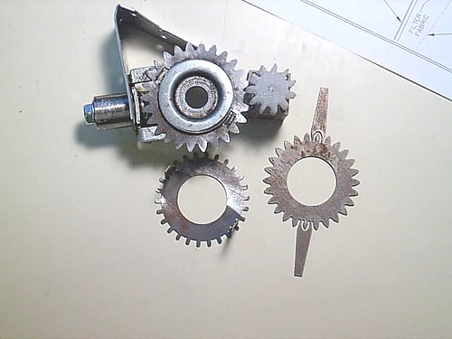
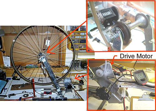
Hello to everybody, here some details about the problem I had to mount JOL (the one with metal gear).

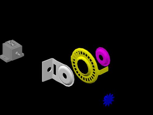
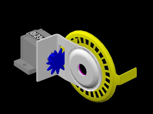
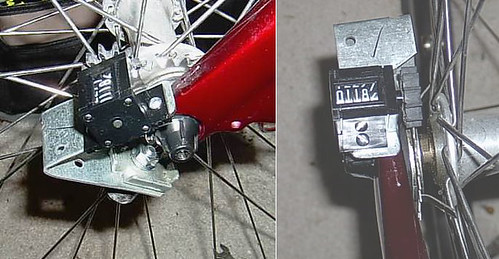
The major problem is related to the assemply wheel's hub / fork.
The space to host the JOL is not enough, only 4.5 mm, if I insert the JOL I'v not anymore place for the fork.

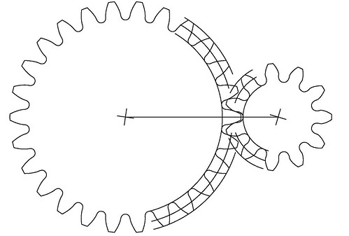
And also to space between the JOL and the spoke is too large, no contact with the JOL gear.

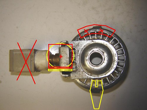
I've try to enlarge the hole of the JOL in order to install it more closer to the spoke, but then the gear guide was disassemby, there was friction to the hub, and also contact to the fork.


This was with my road bike. Was worse with my MTB.

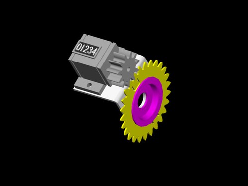
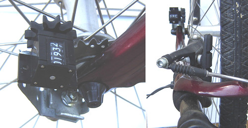
At the end I try with a low cost MTB of my sister and then, with some small modification, the JOL work fine.


As Stu Rigel say, low-tech bikes are quite adequate for road-course measuring, but it's a shame to leave the good one in the garage :-) or to buy a new bike (or only a new wheel) only because we can't mount the counter.

Electronic counter could be a nice solution when it will be accepted as measuring device, this means that must be solved also the back and forward counting.
(I've also a GPS Garmin EDGE 305 mounted, to combine with the JOL measure)

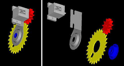
Nice solution could be the "hybrid" with electronic display (i.e.
Veeder-Root A103-001) and mechanical gear. But remain the problem of mounting in some bikes.

In any case, I think you are in the good direction to develop a new counter.

If my input can help you, I don't know, eventually we can furthermore develop a new version of the counter after the release of the next generation you are developping now.

Regards,
Fabio
Fabio,
Thanks for posting the well formatted pics of your problem. I'm not sure, but the modifications I've made to the geometry may allow it to mount to your road bike. I've increased the dish by 2mm, and increased the fork clearance from the JO model by 5mm. The conflict I see is with the cap on the hub. I may only need to increase the diameter of the cup a couple mm to solve the conflict.

I've never seen a cap like that on a hub before. Is it a rubber/plastic piece that can be easily removed? ie. a "beauty ring"? Does it seal in grease, or just add a streamlined look to the axle?
What is the diameter? I scaled it off the picture at 19mm, but this should clear the existing counter you have. Since it doesn't, I'll need some sort of direct measurement.

I'll see about going to a bike shop this weekend, they might have one I can look at.

Thanks again for posting the pics! I'll see what I can do.

Best,
Tom

Add Reply

Post
×
×
×
×
Link copied to your clipboard.
×