
I'm working on a new counter based on the metal gear we've used for years, with a minor modification to aid in assembly. Cost should come in on-par with the old ones.

I've contacted a number of prototyping companies to see if they would be interested in producing the metal gear assembly. Most said they would not be interested because of the highly complex nature and low volume of the pieces.

One manufacurer has expressed an interest, and I sent him my counter to evaluate. I expect an estimate to produce 300 gears sometime in mid-August. Production time will be determined then.

The counter I'm proposing will have an identical ring gear (yellow) and retainer cup (magenta) and a modified baseplate (white).

The remaining gear (blue) should be easy to obtain in low volumes. I need to look into that. My hope is to have all the pieces available in a couple months if the price is right.


Last edited {1}
Original Post

Replies sorted oldest to newest

EASY-READING COUNTER DESIGN CONCEPT


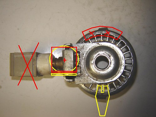
Tom stopped by for a visit last weekend and we had a chance to discuss the evolution of a new counter. We agreed that readability was important, and talked about various ways to achieve it. Tom’s original redesign is almost ready to go, but since initial tooling will be a significant cost Tom decided that it would be best to take some time to be sure that what is finally produced will be the best that he can do.

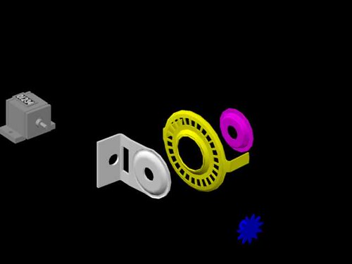
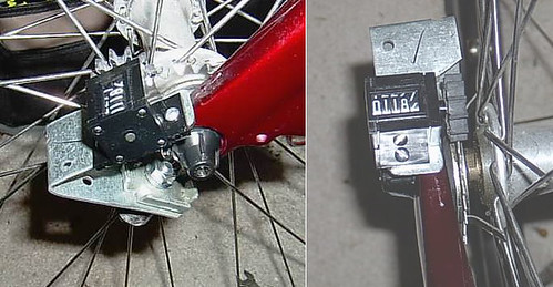
Here is a new concept for a counter design. It is pretty raw now, but Tom is working on a working prototype model.

The new design allows the counter to be read normally (text horizontal) instead of having the numbers appear rotated 90 degrees as in existing counters. You read the counter directly, from left to right.

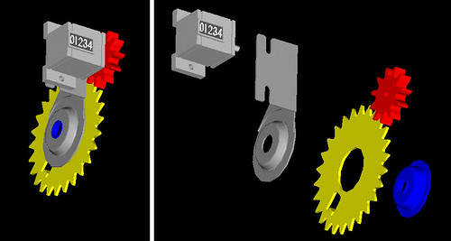
The counter uses the same basic design as at present except for the following:

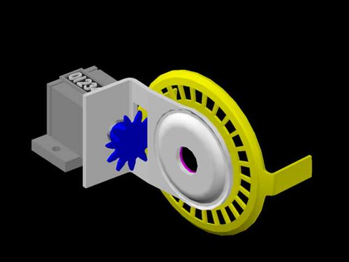
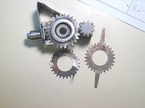
1) The outer rim of the large gear is removed, allowing the protruding stubs to act as driver pins for the delrin gear mounted to the counter shaft.

2) A driving tang is incorporated. It is seen at the bottom of the picture.

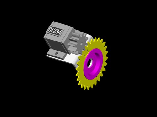
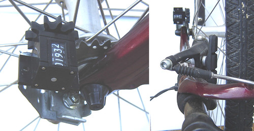
3) The counter is mounted on a bent tab incorporated in the present counter support chassis. In the picture the counter is seen looking at its non-driven end. A gear is mounted to the shaft on the driven end. The readout will be viewed looking at the top of the red square, and the numbers will read from left to right. The view of the readout will be the same as on my chain-driven prototype.

4) A gear ratio of 11/26 is used, giving 23.636363 counts per revolution, the same as with the original Jones/Oerth counter. This odd ratio provides a “hunting tooth” which distributes wear uniformly.

5) The 11 tooth delrin or nylon gear is mounted to the Veeder-Root counter with a small setscrew. Width of the delrin or nylon gear is ¼ inch, to accommodate a certain amount of back-and-forth wobble of the metal driver gear.

6) The counter is mounted in the same way as the original. It is all one assembly.

Tom is preparing a better rendering of the concept.

As Tom works, and I do not, you will see updates coming from me as well as Tom.

Comments on the design are welcome.
Pete, my only concern would be that by mounting the counter parallel to the hub, as opposed to perpendicular as it is now, it would protrude farther and might catch on something, either when riding or loading/unloading the bike. The current design is pretty tight to the bike fork; I've never had much of an issue reading the digits at 90 degrees.
Extra sideways projection is on the order of 1/2 inch or less. This extra may be more prone to catching on things, but not much. It does position the counter better for direct reading, moving the readout a tad farther out from the fork.

With regard to easy reading, I have been using my chain-driven counter for 300 miles now, and I find that it is significantly easier to read while riding. Whatever counter finally evolves, I will never go back to anything that reads sideways. The improvement in reading is enormous. Must be seen to be appreciated.
Last edited by peteriegel
This looks good- but how easily will this translate into a counter that can be read at the handlebars?

I question whether my presbyopic eyes can adjust to reading the counter at the wheel again- even if I can avoid having to turn my head a quarter turn to read the numbers... Smiler

Is there any advantage in changing the gear ratios so that there are more counts per revolution- or, in your opinion, is the device at least as accurate as the method?
The initial goal is to produce a basic counter which is superior to the original. In the design it is intended that the gearbox be adaptable to some sort of cable-driven rig for handlebar mounting. But that is the secondary goal, not the primary.

The Veeder-Root counter has a stated limit of 500 rpm, which translates into 5000 counts per minute. The higher the gear ratio, the smaller is the measured length for one count - giving more precision. But also increasing the speed of the counter.

I haven't heard of anybody destroying a counter by overspeed yet, but from time to time, especially on downhills, we all exceed the design limit of the counter.

See Speed Limits for more on this.
The first generation of gears came in last weekend. I used the chassis from the old counter to test fit the ring rear, and to test gear engagement. Admittedly, it looks a bit klunky, but this will be rectified in the final design.
Several gear profiles were ordered, and tested to see the advantages/disadvantages of the various configurations.


Here are some of the prototype parts.

The gears mesh quite nicely, and run quietly up to about 1500 rpm.
As soon as the counter that's on order is received, I can give it a proper road test. Final production can probably begin in a few weeks.

Tom has a local supplier who can make one-off prototype parts. As the initial tooling cost is likely to be high, Tom has elected to make full-scale mockups, and test them, before contracting to buy the fabricated gears in quantity. Measure twice, cut once.
Last edited by peteriegel
I will be visiting Tom this weekend. We expect to travel to see the fabricator, and hopefully to place an order for 500 gear drives.

Tom has done some protype work to be sure that the gearing runs smoothly. See below:


Raw Prototype Counter

The finished counter will not be the rough thing you see above. This posting is only to assure all that progress is being made.
If the main drive gear is to be made from aluminum (as it appears) you're likely to run into a durability issue with such a thin profile. Even though there's very little stress on the gear, the aluminum will wear down.

A steel gear, on the other hand, will tend to wear a groove into the nylon counter gear.

Making the drive gear wider will alleviate these potential issues, but the material costs go through the roof.
NEW COUNTER PROGRESS

This weekend I visited Tom in Virginia. We traveled to meet the fabricator who will be making the gear assembly. The shop was old and filled with old stamping and bending machines, and shelves full of dies used in previous jobs. We talked with the project estimator and were given a tour of the facility. Both Tom and I came away with a high degree of confidence that these people knew what they were doing. It was a worthwhile trip. We picked the brains of the people who knew more about this kind of metal fabrication then either of us do. As a result, we began work on what we hope will be the design that we will send to them. You can see it below.


AutoCad Assembled and Exploded Views

The design permits the counter to be read with the numbers from left to right, rather than the former sideways top to bottom. The drive gear is driven by a tang bent toward the spokes. It will be long enough for some bikes. A slide-on extension will be provided in case it is not long enough.

Construction will be either galvanized steel, as formerly used, or stainless steel. The metal gauge will be at least as thick as on the former metal gearboxes.

Tom and I have been working on this together, and the collaboration has been fruitful. Tom has expertise in AutoCad, which allows him to do detail drawings on the computer screen. This makes design changes easy, and also allows the fabricator to be sent an electronic AutoCad file, which most modern fabricators seem to like because their machines can be fed the data directly.

Tom also has access to a man who runs a waterjet cutting company, and he has cut out several prototype gears which Tom has been using in his development work. He used these gears to produce the working prototype shown below. A 24 hour run of the counter at 15 mph will be done to be sure there are no unexpected glitches. More as time goes by. We are very close to a final design and placing an order.


This is the Working Prototype.

We have obtained a domain name and will be setting up a web page once the counter drives have been ordered.
Last edited by peteriegel

Add Reply

Post
×
×
×
×
Link copied to your clipboard.
×