
A New Counter Design

One hopes that Paul Oerth will be successful in locating a source for gear drives for Jones/Oerth counters. We will be happy if he does.

Should the hunt be unsuccessful we will have to find something else. The present design is universal in its mounting – it fits almost all bikes. The mounting method is quite effective.

It could be that an effort will have to be made to make dies to punch out the three main parts of the drive. If this must happen, the design can be modified to simplify construction. Below is one way to do it. This is a crude first concept, not a solid proposal. I put it forth hoping to stimulate discussion.


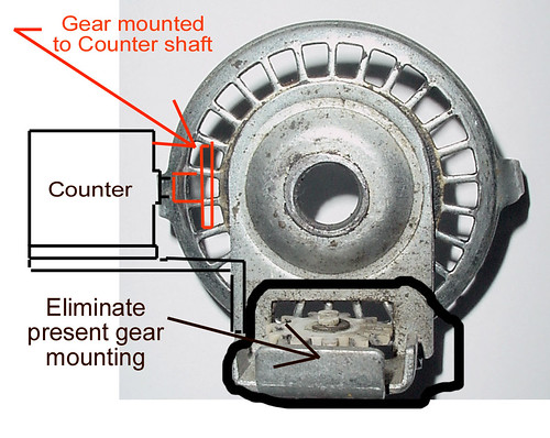
The new design eliminates the present plastic gear and the brass machined sleeve in which it rotates, and also eliminates the white plastic adapter that mates the gear to the counter.

By using an off-the-shelf gear that mounts directly to the counter shaft, the shaft will not have to be squared off.

Let’s see some discussion. We have a problem!
Original Post

Replies sorted oldest to newest

Here's an excellent source for parts, in Australia.

Example of worm gears available:
http://www.smallparts.com.au/cgi-bin/store/datafill.pl?...c-Metric&Step=3=post
Note that metal gears have a minimum production required, so you have to e-mail for pricing information.

The main index:
http://www.smallparts.com.au/cgi-bin/store/product.pl?alpha=ALL=post

If you can't find it here, you don't know what it's called.
Here's a question for you guys:

Any changes you'd like to see to the existing JO counter? Before I go designing something, I'd like to have some input on the pros and cons of the existing design.

Also, does the drive ratio work well enough, or would you like to see more or less counts per wheel rev, or does it matter?

And how much would you pay? Commercial viability is important. The best product in the world is no good if nobody buys it. I'm trying to keep the parts count down, but I have a feeling it's going to cost a lot more than the JO counter.
Last edited by sturiegel
Also, an easy way to disengage the counter from the wheel so I'm not turning, and aging, the counter when I'm just riding my bike. You might be able to do this by replacing the little prongs that fit between the spokes with screws. You just need something that you can move in and out of the way of the spokes.

Finally, a handlebar mount for the readout. I got one from Laurant a while ago and it's great.

But I'm probably not your target audience because I already own one. I probably wouldn't buy another one even with the above features unless I could sell my current one.
As long as you're taking suggestions, the more counts per revolution, the more accurate the measurement.

Let me offer that I am NOT in favor of a reset button. Enough things happen without having to be worried about the button getting accidentally pushed.

A handlebar mounted option is definitely a good thing as well.
We already have a very nice handlebar unit with a reset button, in the form of the electronic counter.

I prefer the non-reset Jones version for recording the data, as the continuous string of data tells a story.

One example - with non-reset, if a measurer does all his calibrations in one direction, because he is afraid of traffic, this will be seen from the data. It's not common, but it happens.

As for counter configuration, the present general layout is robust and has proven successful. If the brass threaded portion is eliminated, to make assembly easier, a flexible shaft drive won't fit on it.

Gear ratio using the present gearing yields 23.636363..... counts per revolution of the bike wheel, and the matchup of the gear teeth is good - better than the original which has 20 counts per revolution. A round number here is not important.
A lot of measuring wheels do their reset with a little knob that you turn. The right-most digit turns to 9 first and stops there. After it stops the next digit starts changing until it gets to 9 and stops, etc. After all digits are 9 they all turn together to 0. I'm sure people have seen this. Not much chance of an accidental reset with that.

Sorry I spelled your name wrong Laurent.
Any thoughts on a straight gear-drive counter, similar to Pete's chain-drive unit?

I'm running into a lot of CNC ops to duplicate the JO, and that means big bucks. Machine time is precious. Simplifying the design will keep it affordable.

Mount a large spur gear to the bike wheel, and a small one to the counter. The only trick there is setting the gear mesh on installation.
quote:
We already have a very nice handlebar unit with a reset button, in the form of the electronic counter.


But then you have to jump into the whole electronic counter thing, and some people don't want to do that.

quote:
I prefer the non-reset Jones version for recording the data, as the continuous string of data tells a story.


I agree, and it also tends to make all the measurements "blind" because it is difficult to tell what the numbers mean during the measurement. But if people are allowed to use electronic counters for certification, it doesn't seem to make sense to me to limit the functionality of mechanical counters in this way.
I have a client that makes parts for people in China. You give them drawings, or a part to copy, and specify things like what it should be made from, how it should be coated etc.

You can also spec a cycles before falure if you want them to do a random test to falure on the parts. (More money)

They have all sorts of aluminum and stamped parts made.

I can get just about any metal or plastic part done. Shipped as parts or assembled with QC.
Mark Neal wrote that he has a JOL (Jones -Oerth-Lacroix) counter and wanted an easy way of disengaging the wheel from the counter. I unscrew the cable from the counter at the axle and then can ride whatever distance I wish then I reattach the cable to continue my ride or to start measuring.


Bernie Conway
"I have never heard of the counter failing."

That's a quote from Peter Riegel who's had about as much experience with counters as anybody, so it most be pretty unusual for counters to fail, but mine did. When it was about to turn over from 999999 to 000000, it didn't; instead, the last ring of numerals kept turning, but the others did not. I dissected the thing (purchased, I believe, in the early 1980s from the Joneses themselves) and didn't see an obvious problem that I could fix. Plus, I pretty much destroyed it taking it apart. The gear-drive parts seem fine, though.

David Reik
I've got a JO counter and have bent the engaging prongs back so they clear the spokes. I then made-up 2 adaptors - these are electrical spade connectors (used in cars and other electrical equipment) and the size I have is a tight fit onto the counter prongs. Onto the barrel part of this connector (the end that accepts the wire for soldering or crimping), I clamp a blue point connector to ewnlarge the adaptor. I can then cycle any distance with the counter mounted and slip-on either 1 or 2 adaptors to engage the spokes when I'm ready to measure. I then remove them to cycle home. Therefore my only counter wear and tear is when I'm actually measuring.
Mark,
Sorry, I don't have any photographs - I don't a digital camera. But if you really want some, I could impose on some friends to provide me with photos and send to you.
The term "slip them on" was just a figure of speech. The fit is quite tight, just like any electrical connection in a car (which if it were loose it would disengage from its spade terminal at the first bump in the road). The counter prongs are just like an electrical spade terminal. It needs a reasonable amount of push or pull to put it on or take it off. It really works a treat for me.
If you are not familiar with the blue point connectors, they are connectors we use in house wiring in Australia where you join cores of power cables in a plastic junction box. They are "floating" connectors. This connector fills-up most of the spare space between the spokes when the adaptor is installed on the counter.
Let me know if you want any photos.
Geoff sent me the drawing of the connectors that he used shown below


With that I was able to find the connector and install it on my counter as shown below


I was not able to find the blue point connectors Geoff talked about, so I just got a different connection that fit into the other end of the first connection. However, the first connection was long enough to engage the spokes so I left it at that. I rode a little bit with the connectors both on and off, and it worked just the way it was supposed to.

Thanks for the great idea Geoff.
Last edited by peteriegel

Add Reply

Post
×
×
×
×
Link copied to your clipboard.
×