
Has any one experience of using the Leica Disto D5 for measuring a 200m calibration course, or by placing at the centre of the calibration course and measuring to the two ends to measure courses up to 400m?

The stated accuracy is within 0.015% better than the standard EEC Class 2 steel tapes which are 0.02%. Also it should be a lot easier than scrabbling around on the wet, even frosty ground banging PK nails in and reading the tape millimeters.

A limitation would be it only measures in straight lines and does not follow undulations, so not suitable for every cal course.

I have been watching these improve in performance and come down in price over the years, and I wonder whether now is the time to buy.
Last edited {1}
Original Post

Replies sorted oldest to newest

The Leica Disto D5 is available in the US. Last September, I purchased one of the laser measurement devices from fltgeosystems.com for about $450 for use in track and field meets. They are also available on ebay.com. The D5 Disto replaced my aging A5 Disto.

The Leica Disto D5 is very accurate and it might be able to measure 200 meters under ideal conditions. To measure a long distance, you would need to mount the unit on an rock steady tripod and shoot at a gray target plate that a helper held in place. Finding the target is not that easy. Image aiming a laser pointer at an 20cm square target that is 200 meters away. The laser beam is difficult to see in the sun. The unit does have a 2.4" color display and a 4x zoom which does help finding the target.

I have used the Laser Disto while measuring courses as a substitute for a tape measure. It comes in handy when measuring in traffic. I have a total station and use it for measuring calibration courses. I never tried to measure a calibration course with the Laser Disto but it may be possible to do so in smaller increments like 100 meters.

Thank you. -- Justin
Justin,

I'm curious how his works. When you mount it on a tripod does it have another laser that shoots straight down to show you where on the ground the end point is? Or does the tripod have a 4th arm that goes straight down that you can use to see this?

I looked in Wikipedia and it says this:
Positioning the tripod and instrument precisely over an indicated mark on the ground or benchmark requires techniques that are beyond the scope of this article.
Mark,

The Leica Disto D5 has a standard 1/4" tripod mount. In order to position the Disto directly over at PK nail, you would need used a plumb bob and a tripod with a plumb hook. The Disto does have a setting for the tripod so you do not need to calculate the offset from the front end or back end of the unit.

You could attach a hook to a camera tripod. Most surveyor's tripods do have a hook for the plumb bob. Some total stations have a built-in laser or optical plummet which may be used in instead of the plumb bob. The laser and optical plummets require the tripod to be level but they are fast to set up and work especially well on windy days.


Surveyor's Tripod

Here are some images of my Disto D5.


Back view showing tripod connector


Front view showing measurement


Laser Disto in Digital Pointfinder mode

Thank you. -- Justin
I decided to purchase a Bosch GLM 250VF since it advertised 250m range compared to 200m of the Leica Disto D5 and also cost about 60% of the D5's price.

It works well on white card out to at least 150m, and I am presently experimenting with cheap clear plastic retroreflectors of the type used on vehicles, to make a target suitable for use at 250m.

I need advice on a cheap way to achieve fine controlled pointing. I purchased with the laser meter the recommended Bosch "Professional" BS150 tripod. Unfortunately, although this has orthogonal adjustments they are just of a simple controlled friction type and even when I slacken off the locking device there is enough friction that the pointing adjustment becomes somewhat fiddly.

The beam has a divergence of about 2 minutes of arc (0.6mrad) so ideally I would like a fine screw pointing adjustable smoothly at the few minute of arc level. My present tripod is only smooth at the 1 degree level. Also, being light (just what I need for carrying on my bike - I don't want a heavy traditional surveyors' tripod) it does flex under the friction force needed to adjust the present pointing system. I reason that if I could get or make a simple screw adjuster to sit between the tripod and the laser meter, it would be a satisfactory solution. I have not been able to find a cheap fine motion device to purchase, so I am thinking of constructing one.

Are there any suggestions?
Mike,

I purchased a D5 a few months ago. I tried it out on the calibration course in front of my house and had the same issue you had with lack of fine adjustment. It is very difficult to point at a target of reasonable size 150 meters away. 150 meters is the key, because you would then be able to measure the 150m from one side and then the other, and you would be done with a 300m cal course without having to move the target.

If you do figure out a fine-adjustment fixture, please post what you purchased or constructed.
Mark,

I have today been making a cardboard model of fine horizontal adjuster, based on the principle of the Barn Door tracker also known as a Haig or Scotch mount.

Here is a top view. It will need a spring to hold the moving platform against the adjusting screw.

Here is a view from the side:


I have not yet worked out how to make the vertical i.e. tilt adjustment. The Bosch GLM250 weight is 0.24kg.

I wonder if the Riegel engineers can come up with some ideas that can be implemented without an engineering workshop.
I measured my first race course around 1980.

At that time the minimum permissible length of a calibration course was ½ mile or 1 km. As with many beginners I was daunted by the prospect of having to steel-tape a calibration course of that length. The nearest calibration course from my home was atop Columbus’ Hoover Dam, and it was somewhat over 3000 feet long, with a PK nail set in the dam concrete. It was 15 miles from home.

At that time I was conferring with a local surveyor who had a number of steel tapes ready to sell. He had never heard of the calibrated bicycle method, and was interested. While we were talking about it I mentioned my reluctance to take on a ½ mile taping job. He offered me the free use of one of his firm’s Wild D13S Distomat total station rigs, complete with target and tripods.

I used the rig to establish a cal course near my house. It was something just over 3000 feet as I recall, and has since been paved over. I now use a 1000 footer in the street in front of my house.

This experience convinced me that a shorter permissible calibration course length would be a boon to measurers, and it came to pass.

I can lay out a 300 meter cal course single-handed in less than a half hour, and I doubt that I’d have an interest in electronic marvels, especially those with calibrations that are simply the unsupported word of the manufacturer.
Last edited by peteriegel
Pete: I've not tried your solo cal course layout. I always had a partner for this. With retirement comes time during the week when my partners work (too bad for them). I have a calibration course near my house but most of the courses I measure these days are 50+ miles away, which means several hours could pass between the final measurement ride and the 2nd calibration. I'm ready to try the solo cal course layout.

I have the instructions you posted in Nov '07 and they are very clear except for the method for applying tension to the steel tape. Can an experienced person do this by "feel"? I've run both eds of the tape and think that careful tensioning by feel would be fine (straight, no kinks, no twists, etc). However, the Calibration Course Application asks for the amount of tension and how applied to the tape. Will "by feel" be an acceptable answer to these questions?

Guido Bros - Pete
"By feel" has little difference in reading from when using a scale. Also, the awkwardness often associated with using a scale is eliminated. Sometimes it takes a third party to hold and read the scale while someone else reads the tape.

In short, I believe, for our purposes, tension by feel is as good as tension by scale.
I agree with Pete regarding both topics in this thread - that "by feel" is fine, IF the person applying the tension has actually measured the desired tension with a spring - and that steel taping is not such an ordeal that all the expense and effort for electronic measurement of a cal course is normally justified. But, I do understand different situations require different methods.

My caution when using the electronic distance finder is that there are no dips or humps in the course. I have a course that has two runoff dips in it. An EDM would not measure this course accurately, since there is added distance going through the dips (just as runners would have the same distance).
A number of interesting points raised - thanks all.

Justin: I played with the Manfrotto 410 in a camera shop on Saturday. I am not really convinced the adjustment is fine enough for what I want. Basically it appears to be designed to position cameras over angle ranges of 90 degrees plus and the knobs are a bit stiff for very fine adjustment at the one minute of arc level. It also rather expensive. I am making slow progress with a home built version .

Pete R: I will be checking the Bosch calibration against my steel tape, in fact they suggest setting up a fixed test range to check the laser on at regular intervals. Incidentally, steel tapes also rely on the manufacturer's certification unless we get them checked at a national measurement bureau which we never normally bother with. Steel tape inter comparisons which I have done invariably show them to be within spec.

Guido Bros: Measurements 50 miles from home are one of the occasions I want to use the laser measurer. I had some last winter in cold and frost and needed on the spot calibration. I no longer feel up to scrabbling around on the ground in such conditions, but I accept the solo method is really excellent if you can do this. I always teach it to new measurers.

Duane: I agree that short scale dips and humps would make course unsuitable for measurement by laser. But If the for example there is a single change of slope then the dip or bump can be measured relative to the laser beam and a geometric correction applied. One metre off in 100 metres amounts to a correction of only 5mm.

My other application is to lay out calibration courses on off road surfaces. We have been getting some queries from races on non-road surfaces who want road race certificates of course accuracy. We are planning to investigate the change of bike cal constant on one such course.
Humps and dips would not really be a problem. I set up my EDM and target on tripods about 500mm above the ground. A hump of more than 500mm will prevent the EDM from seeing the target, and a hump of less than 500mm will result in a negligible change in distance.

A dip of 1 meter in each of two 150m segments would result in a cal course measurement that was 25mm shorter than its true distance. And this would result in slightly longer (very slightly) race courses. The error would be in the "right" direction.
Hi. Okay, I want to use the laser method to lay out my cal course. What are the main things I need to include in my cal course application so the certifier will know it's accurate, and will accept it? What would be a fatal mistake in my application? Thank you.

I think the laser will be faster than the steel tape method, which I familiar with, and will be less prone to human error.
The problem here is that there is NO presently established method to use electronic measurement to lay out cal courses. There are two levels of instrumentation. There is highly-accurate laser equipment, costly and used by surveyors. If asked, a surveyor will be able to produce a certificate attesting to the proper calibration of the individual instrument.

There is also an emerging market in consumer-grade electronic measuring equipment. Its accuracy is unknown to me and, I suspect, to most certifiers. The certifiers must understand the methodology in order to sign the USATF Certificate of Accuracy.

It’s not enough to go out and buy a magic electronic measuring device , use it, and believe that the label on the instrument is proof of accuracy. Without confidence in accuracy, certification is a sham.

Steel tapes have been around for a long time, and experience has shown that they are accurate enough for our purposes.

If you want to use electronic measurement, hire a Registered Professional Surveyor to do the job. He has the proper calibrated equipment and knows how to use it. Of course, he may elect to use a steel tape! It’s hard to shave much time off what is, after all, a half-hour procedure.
quote:
Originally posted by Mark Neal:
Mike,
Any progress on your fine adjustment mount?

Not much I am sorry to say. I have bought a few pieces of hardware - a good hinge, angle aluminium and a threaded rod with 1mm pitch, which I could use for a 1-axis adjustment. But I still have not come up with a design for two axis adjustment which I could make with primitive workshop facilities.

I am still searching for a solution. Recently I saw an equatorial mount for an astronomical telescope on e-Bay. It had two slow motion hand drives working on worms, which were geared at 2 degrees for one 360 deg rotation of the hand knobs, so the laser beam would I think be nicely settable to 1 minute of arc. I bid to my maximum (£46) and this was not sufficient as another bidder had set a higher max bid price and so got it for £47.

I am still very much on the lookout for some way of doing the fine pointing.
Neal,
Yes that is the type of thing I am looking for but that Orion min-EQ sells for £65 including PP in UK. Also I would have to put it on a taller tripod, since one of the objectives is not to have kneel on the dirty ground.
At present I am looking out for second hand systems on ebay: tall tripod plus equatorial mount plus a telescope. I suppose I would throw away the telescope or try to sell it on ebay.
After 4 months I managed to buy an EQ1 Equatorial Telescope Mount with a sturdy tripod on ebay for £24. After a few minutes filing the sloping shoulders of the rectangular slot of telescope mounting point, the Bosch 250m laser range finder fitted snugly secured with rubber bands:

The tripod is much sturdier than the puny one shown in the background of the picture above and which I initially bought for the range finder. The EQ1 telescope mount has proper slow motion drives with hand knobs and is far better than the adjustments on any cheap alt-azimuth mount with friction bearings and a tilt/pan handle to adjust. One adjusts the EQ1 mount for the equator so that the right ascension axis points horizontally in the following configuration:

The right ascension drive is extremely precise. The declination drive does slightly perturb the RA drive setting due to a tiny amount of slop in a bearing, but this does not prevent one doing hand adjustments using the slow motion knobs at the minute of arc level.
The laser beam diverges with an angle of 2 minutes of arc, and alignment with a small reflector target is easy with this mounting arrangement.

My first trial was with a target consisting of a pair of vehicle retro reflectors taped to a post 248 metres away over rough ground. The retro-reflecting surface measured 10 cm by 8cm which was smaller than the laser spot size at this distance - about 15 cm diameter. Alignment is done using a small sighting viewer on the rangefinder, and when the laser spot hits the retro-reflector a bright red spot is visible in the viewer and also with the unaided eye.
The readings I got in this initial trial fluctuated by about 1 or 2 cm - completely adequate reading precision for laying out a calibration course. Not that anyone would have ever laid out a 248 m calibration course with a steel tape over this rough, bumpy ground.

When I tried increasing the range to about 300m, I was not able to get a reading, so maybe the instrument is programmed to reject readings above 250m which is the stated maximum range, or maybe I had alignment problems since I could not see the reflected laser light at the increased range. More tests at ranges greater than 250 m are needed. However, even if range is limited to 250m it will still be very suitable for measuring short calibration courses in a single hop, or longer ones with two measurements.

I have started to evaluate the reproducibility using an 83m distance between a nail, and a small retorreflector of 4 sqcm area on a fence. I can position the laser ranger exactly, within 1 mm over the nail using a plumb bob:


Here is an magnified photo of the laser spot on the retroreflector. I think it appears white rather than red due saturation of the digital camera CCD. The scale is such that the small white patch is 5 cm above the edge of the retroreflector:


At 18 C today the reading came out consistently within 1 mm of 83.259 metres. I shall repeat this set up at other temperatures during the next few days. If reproducibility is confirmed, I will then steel tape a 249m cal course and then measure it with the laser.
I have taken the following series of readings to check for the reproducibility of the Bosch distance meter:

metres temp C date time
83.259 18 24/03/11 03:30 PM
83.256 17 24/03/11 05:00 PM
83.256 8 25/03/11 08:30 AM
83.259 8 28/03/11 08:40 AM
83.256 8 28/03/11 08:55 AM
83.258 10 28/03/11 09:35 AM
83.256 11.5 28/03/11 10:30 AM
83.259 11.5 28/03/11 11:30 AM
83.256 16 28/03/11 04:00 PM

The variation includes both the variation of the instrument, stated to be the sum of +/- 1 mm plus +/- 0.005% of the length, and also the accuracy of positioning the plumb bob over the nail which may be of the order +/- 1 mm.

There is no indication of a significant thermal coefficient in these readings.

These results are rather similar to the reproducibility of a 50m steel tape used in two lengths over 100m, but without the hassle of temp corrections, end corrections and tension measurements as well as scrabbling around on the ground, all of which are needed for steel taping.

The next test will be comparison of measurement of a 250m cal course with the Bosch laser distance meter and with a steel tape.

Here is how I attached the plumb bob to the back of the laser meter:

I'm impressed at the experimental technique. Well done, Mike.

I hope a stranger does not send me an application for certification using unsupported measurement data employing a laser gun. I am not sure I'd know how to find it credible. I'd expect to be asking lots and lots of questions.

I'd certainly have no problem with an application from Mike, but few would document their methodology so well.
I've received a couple cal course applications where the measurement was by Total Station. The only thing in the documentation that really convinced me that the measurement was accurate was the "professional surveyor" by the measurer's name.

I think the only way we could accept this type of measurement is if the measurer has proven ahead of time that he is capable of accurately measuring a course with this technique. That's why I suggested in another thread that we allow EDMs to be used for the second measurement of a cal course. Once a measurer has shown 2 or 3 times that his EDM measurement of cal courses is very similar to his taped measurement of cal courses, he could use only his EDM in the future.

Actually, a better practice would be to allow EDMs for the first measurement, with taping required for the second. Best for them to test the accuracy of their method without knowing what the right answer is.
Pete,
Thanks for your confidence in my work.

I know you are cautious about un-proven techniques, and especially complicated techniques which have plenty of scope for operator mistakes or misunderstandings. Please treat this as work in progress. I am not going to over advocate its use in comparison with the basic tape measuring method. First of all, I have to demonstrate beyond doubt that the device can give reliable results. Then if it proves reliable, I expect to use it myself to avoid scrabbling around on the ground and to layout calibration courses much more quickly than I can with solo taping. If I can layout a calibration course quickly, I will be more likely to do so on the site of a distant course measurement, rather than relying on using my home calibration course and sometimes suffering large temperature changes when the journey is lengthy.

I have more progress to report today:
I located a quiet piece of road about 330 m long suitable for a calibration course. I will call it Allotment Road, Abingdon. The road has a locked vehicle gate which is occasionally opened by people visiting their allotments. There are occasional pedestrians. It is very suitable for firing a class I laser along the road without dazzling road users.

I steel taped a 249.90575 metre calibration course using the standard solo method. This took about 1hr and 40 minutes. I am afraid I am not as fast as you Pete when you quote 30 mins to measure a cal course. That time might be just possible if I had a team of 2 helpers to hook/unhook the end and to tension the tape, and if I was more rapid when getting on the ground to take the reading - but I think anyone would be hard pressed do two solo measurements in 30 mins.

Next I set up the retro reflector at the far end and the laser range finder at the end nearest my car. Took a series of measurements which varied by less than +/- 2 mm, and then packed up the equipment this took 25 minutes - about 4 times faster than my solo steel taping.

Here is a view down the course with the laser spot visible to the eye (bright red) and the camera (small white spot).

The laser gave 249.942 m. Two corrections are required.
+ 0.016 (plumb bob offset)
- 0.003 (slope correction. Laser 1.25m higher than reflector - I have assumed road is horizontal - this needs testing by means of a similar measurement from the far end)

Corrected laser measurement for distance between course end nails: 249.955 m

So the laser gives a result 49 mm longer than the steel tape. This is about half a Jones count, or 0.02%.
My tape is a class II tape specified accurate to 0.02%.
The Bosch GLM250VF is stated to be accurate to 0.005% under favourable conditions.

My preliminary conclusion is that since the difference of the two measurements lies within the sum of the accuracy specs ie 0.025%, I have confirmation that the method works within the advertised calibration accuracy of the instruments.

Much more work to do, but on returning home I found that a job lot of 60 retroreflectors measuring 12 cm x 8 cm had arrived:

I can now set up many targets!

I decided to make my home laser test range better, extending it from 83m to 93m. With the target mounted higher in the tree the beam clears any parked cars, so it should now be usable at any time. The plan would be to test the laser on this short range before and after going to make a measurement elsewhere. It will be a lot quicker than deploying the equipment on the Allotment Road calibration course every time. So the first aim will be to show consistent measurements at Allotment road, and for each occasion to take checks on the 93m laser test range.
Mike wondered how I can lay out 300 m in a half hour, single-handed.

The trick is to traverse the cal course only once, not twice. I use a tape that is marked with metric scale on one edge and decimal feet on the other edge. By reading each, I get two measurements in one pull, with the readings not expected to agree. The same procedure could employ two tapes hooked over the same nail. By having the tapes use different scales, this reduces the chance of making the same reading mistake on both measurements.

If I should make a reading error I will not find it until I work out the measured lengths upon completion of the taping. This is the reason I don't pull out the nails until I have checked the work.

When one measures in both directions, the memory of the previous reading is gone, and it is unlikely that the same reading error will occur.
quote:
Originally posted by Pete Riegel:
The trick is to traverse the cal course only once, not twice. I use a tape that is marked with metric scale on one edge and decimal feet on the other edge. By reading each, I get two measurements in one pull

Now that is a really good idea. My tape does have both scales, but not everyone will have chosen that type of tape marking.

So is this accepted as two proper measurements for IAAF/AIMS international measurement purposes?

If so, would a modification of the principle by taking a camera shot of the reading also be a suitable way recording results without the possibility of error? (One hand holding the camera, the other hand tensioning the tape with a spring scale.)
Mike,

I don't know whether it is specifically accepted or not. As far as I can see, pulling the tape twice and getting two readings would constitute two measurements. But, because of a possible tendency to read the same thing wrong, when doing it a few seconds apart, I felt that using the metric/imperial scales would be a good check. The mind does not instantly convert the distance, so there is no lingering knowledge of a "correct" reading - thus the two measurements are independent.

At least that's the way I see it.

Your camera idea is a good check. I don't use a spring scale.
My response would be that, taking two readings with one pull does not ascertain that the proper amount of tension has been placed on the tape. Two separate measurement actions would go further to assure that the proper tension was applied. Similarly, if, by chance, the beginning end of the tape (opposite the end being read) happened to slip a quarter-inch (or 1 cm) due to pavement giving-way, you wouldn't have a second measurement to cross-check against.

Simply reading two indicators with one pull only verifies one aspect of the measurement. If we put two counters on a bike, and read them both at each split (and overall length), we would only verify counts for the path ridden; it does not verify that the ridden path was the SPR. I think pulling once and reading two different scales (metric and SAE) is not a good indicator that all the variables have been double-checked.
Two pulls are used. The tape is pulled and read. I put down the end and write down the reading. The I do a new pull, and a new reading, using a different scale.

If a nail should pull loose (which is unlikely) it will show up when the two readings are compared. I believe I'd feel it give when I pulled the tape. In any case, is it really likely that the nail would move just a little? It it was that loose it would simply pull out of the pavement. This I'd be sure to notice.

As for tension, pulling by feel is good enough.

Use of the two different scales makes this method robust. When using only one scale there is a tendency to repeat wrong readings.

I believe the solo method, as I've done it, fulfills the requirement for two independent measurements.

See the example below for actual data.

Solo Example
Last edited by peteriegel
I have come up with a new mounting arrangement for my Bosch GLM250 VF. I removed the tripod legs from my equatorial mount, and attached it directly on a piece of wooden floor board which has been shaped to wedge securely on my bicycle rack so that the bike, propped on its kick stand, provides a stable mounting, with the eyepiece at a convenient 105 cm above the ground.

With this arrangement it is easy to jump on the bike and ride it along a calibration course longer than 250 metres in order to very quickly obtain readings on different sections. Even small adjustments of position become very much quicker than moving a tripod. I just wheel the bike along, put down the kick stand aim and take a reading.

For transport to and from a calibration course, the mount packs away in my pannier bag, and my retro reflector target is clipped onto the rack:


I have not timed myself yet, but I should think that on arrival at an already nailed calibration course I can now set up, measure, and pack up in between 5 and 10 minutes. I certainly beats my measured speed of solo taping: 1 hour 40 minutes reported earlier in this thread. Also at no point do I have to kneel on the ground; I just bend slightly to place the box carrying the retro-reflectors over one nail and to check the alignment of the plumb bob on the nail at the other end.
Just a year ago in the previous post I showed my set up for using my Bosch Laser Rangefinder on my bike. It worked well. But could I rely on the results? An opportunity to test it against a calibrated tape came up last June.

When David Katz was preparing to come to London to oversee for the IAAF the official measurement of the London Olympic marathon he purchased a new steel tape and had its calibration checked at the NIST in Maryland (see his post here)

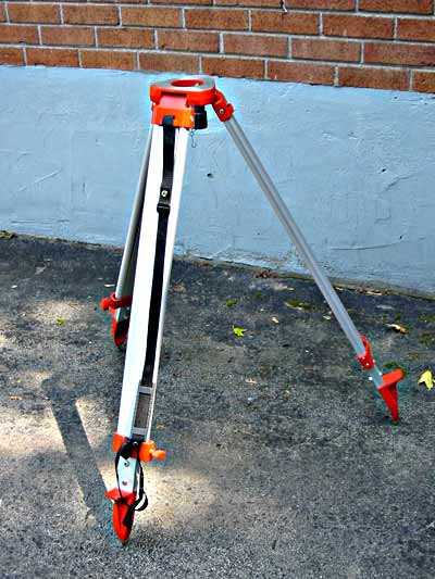
Realising this would be an excellent opportunity to check my laser rangefinder method against a calibrated tape, I took my Bosch Laser and the setup for my bike with me when I went to join David and Hugh Jones for the marathon measurement on 13 June 2012. David and Hugh had measured the calibration course in The Mall before I arrived. After we had finished our measurement ride, I checked the calibration course length with my laser. At first the results were in fair agreement.

While at The Mall for the measurement I was told by David and Hugh that the result from their steel tape measurement was 328.57 m
I went home and worked applied Pythagoras to my raw laser readings to correct for the sloping beam and obtained 328.621 m.
LASER - TAPE = 51 mm 0.015%

This difference was slightly more than the 0.005% to 0.013% error that was claimed by Bosch for the laser, but not by so much to be of concern or cause too much worry about the calibration course length.

When I sent my numbers to Hugh he reported that they had first used the NIST correction for the whole 100m tape rather than the 60m tape lengths which they had used. The corrected NIST calibration steel tape result should be 328.56m.
My initial laser ranger result was 328.621 m.
The difference was getting slightly larger: now LASER - TAPE = 61 mm 0.019%

I asked questions about the steel tape tension and temperature and the correct NIST calibration to use for the Steel Tape.
I was told the Steel Tape was pulled at an estimated 10 lbs. However it was clear from what David told me on the phone after he returned to New York, that the NIST calibration figures which had been so far been applied were for 10 kg tension.

As a result David changed The Mall Calibration Course steel tape result to 328.517 m.
My initial laser ranger result remained at 328.621 m.
The difference was now much worse. LASER - TAPE = 104 mm 0.032%

At this point I became worried about my laser measurement methodology, so I performed a new calibration course layout at home, reproducing the method I had used on The Mall and I photographed every stage. It is written up 
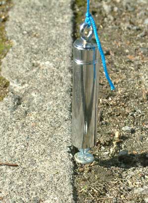
here. I worked out some further very small corrections additional to the simple correction for beam slope which I had initially used. I then applied these corrections to the laser result from The Mall. The overall effect was to increase my Mall result by 10 mm. This was principally due to my previous omission of a 12 mm misalignment of the plumb bob with the marker on the road when I was measuring the East end of The Mall cal course. My son Geoffrey, assisting me, had clearly recorded this in my notebook. When we lined up the bike there had been a small offset which we measured and recorded rather than fiddle again with the bike position. Unfortunately the overall effect was to add 10 mm to the laser result and so increase the the difference between tape and laser.

The Mall laser ranger result was initially 328.621 m, now was changed to 326.631 m. Latest steel tape calculation is 328.517 m.
LASER - TAPE = 114 mm 0.034%

At 0.034% the discrepancy was much more then could be explained from the laser manufacturer's figure for error. The effect on the marathon if we were to use the laser result for The Mall calibration would be to reduce the length we had calculated from our measurement rides by 14 m, which was still quite a bit less than the 42 m SCPF, so it would probably not render the marathon short.

However an unexplained discrepancy of this magnitude would be a worry for me that would prevent me from trusting the laser method in future.

Fortunately the reason became clear early in July when David sent his calculation of the steel tape corrections together with his draft measurement results to Pete Riegel for checking. Pete saw that the tension correction had been applied in the wrong direction.

Mall Calibration Course steel tape result was changed to 328.597 m. Final laser ranger result 328.631 m.
LASER - TAPE = 34 mm 0.010%

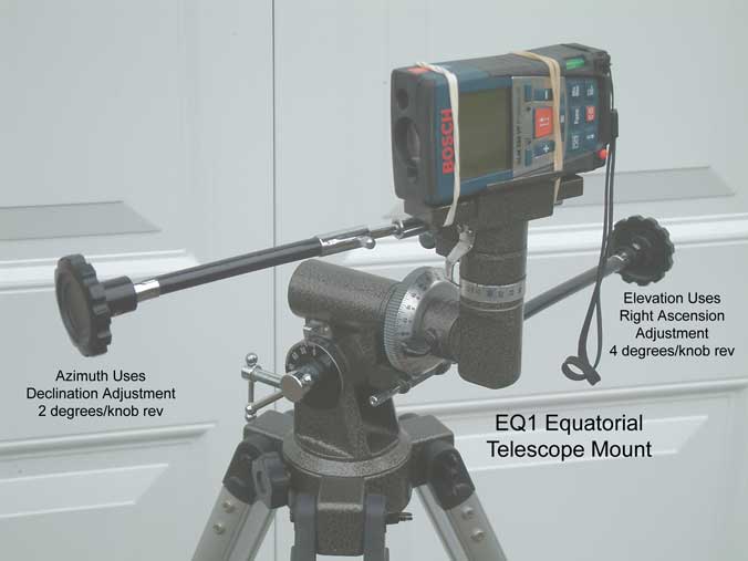
The specification for the laser, a Bosch Professional GLM 250VF, is as follows:

In unfavourable conditions (e.g. at intense sunlight or an insufficiently reflecting surface), the maximum deviation is ±20 mm per 150 m. In favourable conditions, a deviation influence of ±0.05 mm/m must be taken into account.

This spec is 0.013% in unfavourable conditions and 0.005% in favourable conditions. (There was low sun shining almost perpendicularly on to the target reflector during when I used the laser on The Mall, so it is reasonable to assume that the conditions were somewhat unfavourable.)

This was now a very satisfactory agreement with and NIST calibrated tape. Taken in conjunction with previous comparisons between the laser and my own class 2 steel tape which itself had in the past been compared with several other tapes, I now conclude that the soundness of my laser rangefinder measurement method has been demonstrated beyond all reasonable doubt - at least for my my particular instrument, the Bosch Professional GLM 250VF.

As far as the The Mall Calibration Course we all agreed to take the final steel tape value of 328.597 m as derived here for the calculation of the marathon course.
One might want to consider paying a land surveyor in the local area to install a straight baseline. Typical cost for a single party chief for less than an hr is probably less than $125. You just want to make sure he shoots the line at least 8 times and has broken his setup at least twice. They can stop on the way to another job and take care of your needs. Money well spent on experienced personnel.
About 15 years ago I laid out a 1/2 mile cert course on the road outside my house.
The road is dead straight, level and just over 1/2 mile long. I decided to do a 1/2 mile cert course.

The idea being that any error in a cert course would be multiplied as one scaled up to the race distance. If a 1/2 mile cert course was as much as 6" out that would only end up with a three feet error at 5K.

Additionally riding that distance on the cert course would be very similar to riding on the race course. One rides differently when looking down than up into the distance.

And any fractional error from the discreet digits on a Jones counter would be negligible on that distance.

For years I have wanted to validate my 1/2 mile cert course. However redoing the two steel tape measurements by the same method would only confirm any error in method or any error in the length of my tape.

Over the years asked various survivors working on my street if they would help.

I have had various answers from my equipment cant shoot that distance, to hire us and book a job, to sod off.

However today two very nice gents were surveying for a house sale a few houses away. I can spot a shiny new high end survey rig, and knew this was good crew to ask. They were happy to help.

After confirming their equipment would have no problem with 1/2 a mile, I went out by bicycle and placed cones over the marks.
Then lent the bike to his man who biked out to hold the reflector pole. (Accurate pole with bubble level). This was shot from their high end TDR system. Not a GPS based system, so no GPS errors.

I was flabbergasted when they told me the result.

With no prompting or suggestion from me on what I expected, they reported 2,640.17 feet.

It took three people the best part of a day to do the orignal measurements. Took a good tape loaded with a spring gauge, sturdy nails at each point, and a table of corrections for the error or correction at each nail. 2 inches off in 1/2 mile.

Will spend the rest of the day feeling rather validated.
Last edited by jamesm
Great story, James. Thanks for sharing. All us technocrats here will be quick to point out that the 2640.17 value is in FEET, hence, the measured error is not 1/4 inch but 2.04 inches. Still, that's not bad for the long course! There's nothing like a good, certified, steel tape for engendering confident accuracy. Nice work.

JJ

Add Reply

Post
×
×
×
×
Link copied to your clipboard.
×