Has any one experience of using the Leica Disto D5 for measuring a 200m calibration course, or by placing at the centre of the calibration course and measuring to the two ends to measure courses up to 400m?

The stated accuracy is within 0.015% better than the standard EEC Class 2 steel tapes which are 0.02%. Also it should be a lot easier than scrabbling around on the wet, even frosty ground banging PK nails in and reading the tape millimeters.

A limitation would be it only measures in straight lines and does not follow undulations, so not suitable for every cal course.

I have been watching these improve in performance and come down in price over the years, and I wonder whether now is the time to buy.
Last edited {1}
Original Post

Replies sorted oldest to newest

The Leica Disto D5 is available in the US. Last September, I purchased one of the laser measurement devices from fltgeosystems.com for about $450 for use in track and field meets. They are also available on ebay.com. The D5 Disto replaced my aging A5 Disto.

The Leica Disto D5 is very accurate and it might be able to measure 200 meters under ideal conditions. To measure a long distance, you would need to mount the unit on an rock steady tripod and shoot at a gray target plate that a helper held in place. Finding the target is not that easy. Image aiming a laser pointer at an 20cm square target that is 200 meters away. The laser beam is difficult to see in the sun. The unit does have a 2.4" color display and a 4x zoom which does help finding the target.

I have used the Laser Disto while measuring courses as a substitute for a tape measure. It comes in handy when measuring in traffic. I have a total station and use it for measuring calibration courses. I never tried to measure a calibration course with the Laser Disto but it may be possible to do so in smaller increments like 100 meters.

Thank you. -- Justin
Justin,

I'm curious how his works. When you mount it on a tripod does it have another laser that shoots straight down to show you where on the ground the end point is? Or does the tripod have a 4th arm that goes straight down that you can use to see this?

I looked in Wikipedia and it says this:
Positioning the tripod and instrument precisely over an indicated mark on the ground or benchmark requires techniques that are beyond the scope of this article.
Mark,

The Leica Disto D5 has a standard 1/4" tripod mount. In order to position the Disto directly over at PK nail, you would need used a plumb bob and a tripod with a plumb hook. The Disto does have a setting for the tripod so you do not need to calculate the offset from the front end or back end of the unit.

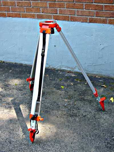
You could attach a hook to a camera tripod. Most surveyor's tripods do have a hook for the plumb bob. Some total stations have a built-in laser or optical plummet which may be used in instead of the plumb bob. The laser and optical plummets require the tripod to be level but they are fast to set up and work especially well on windy days.


Surveyor's Tripod

Here are some images of my Disto D5.


Back view showing tripod connector


Front view showing measurement


Laser Disto in Digital Pointfinder mode

Thank you. -- Justin
I decided to purchase a Bosch GLM 250VF since it advertised 250m range compared to 200m of the Leica Disto D5 and also cost about 60% of the D5's price.

It works well on white card out to at least 150m, and I am presently experimenting with cheap clear plastic retroreflectors of the type used on vehicles, to make a target suitable for use at 250m.

I need advice on a cheap way to achieve fine controlled pointing. I purchased with the laser meter the recommended Bosch "Professional" BS150 tripod. Unfortunately, although this has orthogonal adjustments they are just of a simple controlled friction type and even when I slacken off the locking device there is enough friction that the pointing adjustment becomes somewhat fiddly.

The beam has a divergence of about 2 minutes of arc (0.6mrad) so ideally I would like a fine screw pointing adjustable smoothly at the few minute of arc level. My present tripod is only smooth at the 1 degree level. Also, being light (just what I need for carrying on my bike - I don't want a heavy traditional surveyors' tripod) it does flex under the friction force needed to adjust the present pointing system. I reason that if I could get or make a simple screw adjuster to sit between the tripod and the laser meter, it would be a satisfactory solution. I have not been able to find a cheap fine motion device to purchase, so I am thinking of constructing one.

Are there any suggestions?
Mike,

I purchased a D5 a few months ago. I tried it out on the calibration course in front of my house and had the same issue you had with lack of fine adjustment. It is very difficult to point at a target of reasonable size 150 meters away. 150 meters is the key, because you would then be able to measure the 150m from one side and then the other, and you would be done with a 300m cal course without having to move the target.

If you do figure out a fine-adjustment fixture, please post what you purchased or constructed.
Mark,

I have today been making a cardboard model of fine horizontal adjuster, based on the principle of the Barn Door tracker also known as a Haig or Scotch mount.

Here is a top view. It will need a spring to hold the moving platform against the adjusting screw.

Here is a view from the side:


I have not yet worked out how to make the vertical i.e. tilt adjustment. The Bosch GLM250 weight is 0.24kg.

I wonder if the Riegel engineers can come up with some ideas that can be implemented without an engineering workshop.
I measured my first race course around 1980.

At that time the minimum permissible length of a calibration course was ½ mile or 1 km. As with many beginners I was daunted by the prospect of having to steel-tape a calibration course of that length. The nearest calibration course from my home was atop Columbus’ Hoover Dam, and it was somewhat over 3000 feet long, with a PK nail set in the dam concrete. It was 15 miles from home.

At that time I was conferring with a local surveyor who had a number of steel tapes ready to sell. He had never heard of the calibrated bicycle method, and was interested. While we were talking about it I mentioned my reluctance to take on a ½ mile taping job. He offered me the free use of one of his firm’s Wild D13S Distomat total station rigs, complete with target and tripods.

I used the rig to establish a cal course near my house. It was something just over 3000 feet as I recall, and has since been paved over. I now use a 1000 footer in the street in front of my house.

This experience convinced me that a shorter permissible calibration course length would be a boon to measurers, and it came to pass.

I can lay out a 300 meter cal course single-handed in less than a half hour, and I doubt that I’d have an interest in electronic marvels, especially those with calibrations that are simply the unsupported word of the manufacturer.
Last edited by peteriegel
Pete: I've not tried your solo cal course layout. I always had a partner for this. With retirement comes time during the week when my partners work (too bad for them). I have a calibration course near my house but most of the courses I measure these days are 50+ miles away, which means several hours could pass between the final measurement ride and the 2nd calibration. I'm ready to try the solo cal course layout.

I have the instructions you posted in Nov '07 and they are very clear except for the method for applying tension to the steel tape. Can an experienced person do this by "feel"? I've run both eds of the tape and think that careful tensioning by feel would be fine (straight, no kinks, no twists, etc). However, the Calibration Course Application asks for the amount of tension and how applied to the tape. Will "by feel" be an acceptable answer to these questions?

Guido Bros - Pete
"By feel" has little difference in reading from when using a scale. Also, the awkwardness often associated with using a scale is eliminated. Sometimes it takes a third party to hold and read the scale while someone else reads the tape.

In short, I believe, for our purposes, tension by feel is as good as tension by scale.
I agree with Pete regarding both topics in this thread - that "by feel" is fine, IF the person applying the tension has actually measured the desired tension with a spring - and that steel taping is not such an ordeal that all the expense and effort for electronic measurement of a cal course is normally justified. But, I do understand different situations require different methods.

My caution when using the electronic distance finder is that there are no dips or humps in the course. I have a course that has two runoff dips in it. An EDM would not measure this course accurately, since there is added distance going through the dips (just as runners would have the same distance).
A number of interesting points raised - thanks all.

Justin: I played with the Manfrotto 410 in a camera shop on Saturday. I am not really convinced the adjustment is fine enough for what I want. Basically it appears to be designed to position cameras over angle ranges of 90 degrees plus and the knobs are a bit stiff for very fine adjustment at the one minute of arc level. It also rather expensive. I am making slow progress with a home built version .

Pete R: I will be checking the Bosch calibration against my steel tape, in fact they suggest setting up a fixed test range to check the laser on at regular intervals. Incidentally, steel tapes also rely on the manufacturer's certification unless we get them checked at a national measurement bureau which we never normally bother with. Steel tape inter comparisons which I have done invariably show them to be within spec.

Guido Bros: Measurements 50 miles from home are one of the occasions I want to use the laser measurer. I had some last winter in cold and frost and needed on the spot calibration. I no longer feel up to scrabbling around on the ground in such conditions, but I accept the solo method is really excellent if you can do this. I always teach it to new measurers.

Duane: I agree that short scale dips and humps would make course unsuitable for measurement by laser. But If the for example there is a single change of slope then the dip or bump can be measured relative to the laser beam and a geometric correction applied. One metre off in 100 metres amounts to a correction of only 5mm.

My other application is to lay out calibration courses on off road surfaces. We have been getting some queries from races on non-road surfaces who want road race certificates of course accuracy. We are planning to investigate the change of bike cal constant on one such course.
Humps and dips would not really be a problem. I set up my EDM and target on tripods about 500mm above the ground. A hump of more than 500mm will prevent the EDM from seeing the target, and a hump of less than 500mm will result in a negligible change in distance.

A dip of 1 meter in each of two 150m segments would result in a cal course measurement that was 25mm shorter than its true distance. And this would result in slightly longer (very slightly) race courses. The error would be in the "right" direction.
Hi. Okay, I want to use the laser method to lay out my cal course. What are the main things I need to include in my cal course application so the certifier will know it's accurate, and will accept it? What would be a fatal mistake in my application? Thank you.

I think the laser will be faster than the steel tape method, which I familiar with, and will be less prone to human error.
The problem here is that there is NO presently established method to use electronic measurement to lay out cal courses. There are two levels of instrumentation. There is highly-accurate laser equipment, costly and used by surveyors. If asked, a surveyor will be able to produce a certificate attesting to the proper calibration of the individual instrument.

There is also an emerging market in consumer-grade electronic measuring equipment. Its accuracy is unknown to me and, I suspect, to most certifiers. The certifiers must understand the methodology in order to sign the USATF Certificate of Accuracy.

It’s not enough to go out and buy a magic electronic measuring device , use it, and believe that the label on the instrument is proof of accuracy. Without confidence in accuracy, certification is a sham.

Steel tapes have been around for a long time, and experience has shown that they are accurate enough for our purposes.

If you want to use electronic measurement, hire a Registered Professional Surveyor to do the job. He has the proper calibrated equipment and knows how to use it. Of course, he may elect to use a steel tape! It’s hard to shave much time off what is, after all, a half-hour procedure.
quote:
Originally posted by Mark Neal:
Mike,
Any progress on your fine adjustment mount?

Not much I am sorry to say. I have bought a few pieces of hardware - a good hinge, angle aluminium and a threaded rod with 1mm pitch, which I could use for a 1-axis adjustment. But I still have not come up with a design for two axis adjustment which I could make with primitive workshop facilities.

I am still searching for a solution. Recently I saw an equatorial mount for an astronomical telescope on e-Bay. It had two slow motion hand drives working on worms, which were geared at 2 degrees for one 360 deg rotation of the hand knobs, so the laser beam would I think be nicely settable to 1 minute of arc. I bid to my maximum (£46) and this was not sufficient as another bidder had set a higher max bid price and so got it for £47.

I am still very much on the lookout for some way of doing the fine pointing.

Add Reply

Post
×
×
×
×
Link copied to your clipboard.
×